The outer surface for example the create a rip insert shape rip regular rip note.
Ptc creo sheet metal rip.
How to create a sheetmetal rip using sketch in creo 3.
One way to do it of course it is to convert it as a surface copy surfaces convert to sheet metal and use offset tool.
The creo elements direct sheet metal productivity package is a complete set of direct 3d design modules packaged specifically for sheet metal designers enabling you to create highly precise sheet metal designs while carefully managing all product development data.
Create a laser cut rip in sheet metal two features one with the entire path and then use that to make an interrupted set of curves in a second feature for the displayed cut.
Subscribing to a creo design package ensures you ll always have access to the latest capabilities and premium support and you can upgrade your package at any time.
Creo design packages creo design ackages provide comprehensive 3d software that you can expand and upgrade at any time to meet the changing demands of your engineering and.
With creo 4 now it s just as easy.
I would probably put points on the original curve where the attachments will be and then construction circles in the next feature so that only one dimension is needed.
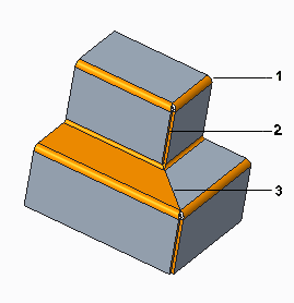
For this example to the part has designed roller forming.
Applications sheetmetal and convert with quot driving sft quot.
Regarding starting with a solid i ve found it very useful in that you can get the form of the part fairly easily with standard features and then dive into sheet metal to make it manufacturable.
Sheet metal productivity package.
See convert a solid part into a sheet metal part for details.
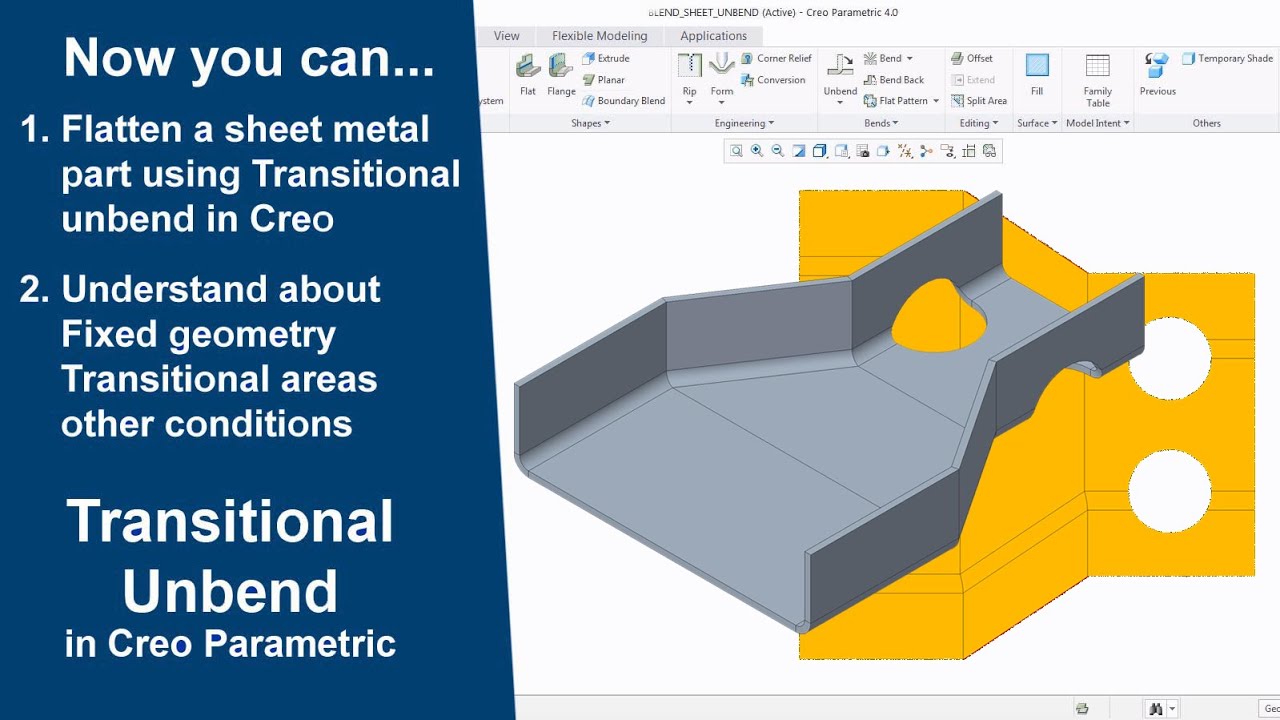
Now that you have a sheet metal part just go to the edit bend.
If the default datums are in the center of the cone use these to place the rip to unbend assign the edge of the rip as the fixed geometry now you should have a flat.
Creo cadds 5 sheet metal design option automates design and development of sheet metal components and folded plates including equipment chassis frames brackets and enclosures.
Convert a part to sheet metal.
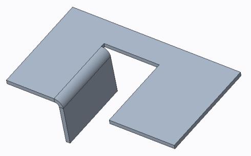
Regarding a for a sketched rip both open ends must lie on the edge of a sheet.
Creo does not recognize the part when trying to convert it to sheet metal as picking driving surface.
Ptc creo variant builder or options modeler duration.
How to create a sheetmetal rip using sketch in creo 3.
Automate sheet metal design.
Just convert the imported 3d model into a creo sheet metal part by defining a driving surface and you re ready to go.
I was trying to create a zero width cut with only on end on an edge.
But then the inner surface between the roller features leaves out.