Paul sobejko s suggestion is correct and to work through the reason each bend in sheet metal stretches the metal.
Ptc sheet metal flat vs flange.
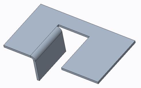
Below is the basic example of the flat and flanged walls.
Constant flat length ensures that the length of the unfolded wall is not changed.
Then you can show that axis in the drawing.
Flat patterns deformation allowance bend tables working in both flat and as designed states and full associativity between part drawing and flat state.
Sorry to say but i thought this was a cool feature but it came totally useless to me as i cannot show the bending axis as in a regular flange wall.
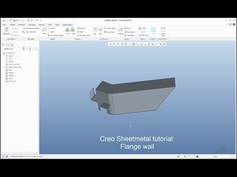
View the full course.
The perimeter is curved and there are a lot of relief cuts in the part.
A ptc technical support account manager tsam is your company s personal advocate for leveraging the.
In the formed section this happens three times so creo would have to remove two extra bend allowances to make the part flat.
72 1 8 is slight short 5 72 may not be exact.
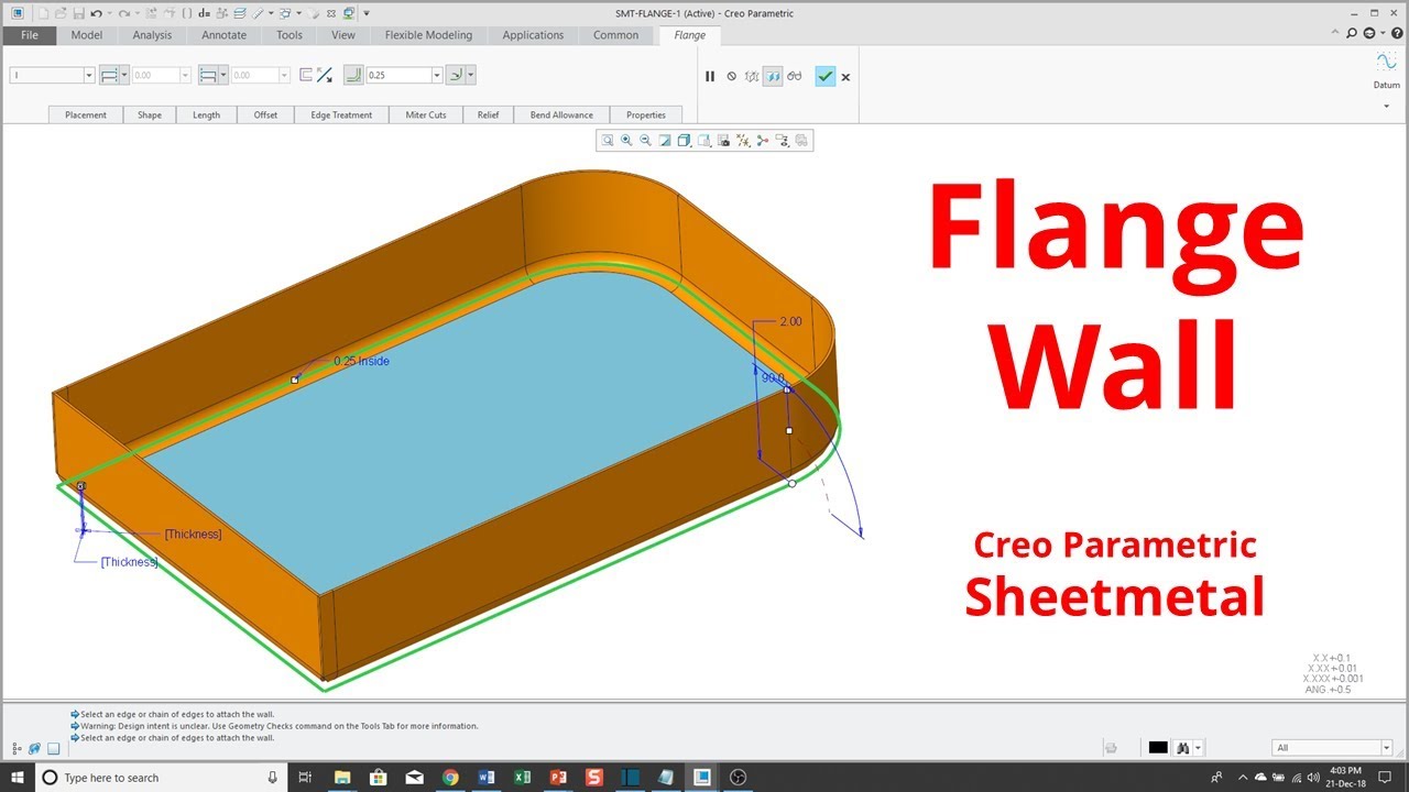
Information regarding the difference of flange and flat wall features for sheet metal.
Flange wall gives you control over the cross section of the wall.
Changing a bend with the constant flat length option selected.
Constant flange length keeps the distance between the apex and the end of the wall fixed.
In creo if you use a form tool feature it will not account for the additional material in the flat pattern.
Hi everyone i m trying to model a sheet metal part with a complex flange around its perimeter.
This part is either coined or rolled with a hem tool.
In the primary corner this happens once.
Views 671 views difficulty level introductory jim barrett smith ptc.
When modeling sheet metal you always have to be aware of the process used to fabricate the part.
Specifically topics covered include.
Challenge modeling complex curved sheet metal flange also note that this is certainly not the highest level of integration.
Flat wall gives you control over the profile of the wall.
Flange is improved in sheetmetal design.
The picture shows the part and the tool that is is formed on.
The results should be similar.
I already have the flat pattern geometry including the flange.
I did some iterations to get the numbers to match ie.
Here is the basic explanation for the two sheet metal options.
That s what forms the gap is a rip is added the subtraction of.
Information regarding the difference of flange and flat wall features for sheet metal.
Edge treatment is improved when defining a flange feature.
It purely depends upon the shape of the part that decides which one to use.
Pro e showed to be very inconsistent here with this.
This tutorial is part of a course.